M9 & M11 Pressure / Temperature Potentiometers Adjustments
|
EQUIPMENT ALERT
The pressure zero, pressure range, and temperature potentiometers cannot be adjusted
separately. If one potentiometer needs adjusted, then the entire potentiometer adjustment
procedure must be performed, and it must be performed in the proper sequence as follows:
|
(1) Remove right hand side panel.
(2) Open sterilizer door.
|
DANGER
The following steps require the sterilizer to be plugged in to power while the adjustment is
being performed. Do not touch any components except for the adjusting screw of the potentiometer.
Failure to comply with these instructions could result in an electrical shock, which could result
in severe personal injury or death.
|
NOTE
After the following step is performed, the display PC board lamps will individually illuminate and then
extinguish one at a time in a left to right sequence. When all the lamps have illuminated and extinguished,
proceed with step 4.
|
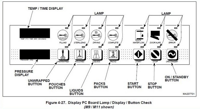
(3) Press and hold down the LIQUIDS and PACKS buttons simultaneously while connecting the power cord to the sterilizer
(See Figure 4-27). Release the LIQUIDS and PACKS buttons.
NOTE
When each button is pressed, its corresponding lamp will illuminate and stay illuminated. Also, after the
following step, the PRESSURE (PSI) display will display the pressure that the control PC board is reading
and the TEMP (°F) / TIME (MIN: SECONDS) display will display the temperature that the control PC board is
reading. When each button has been pushed, proceed with step 5.
|
(4) Press and release the UNWRAPPED, POUCHES, LIQUIDS, PACKS, START, STOP, AND ON/STANDBY buttons one at a time
and in this order.
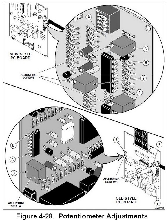
(5) Turn adjusting screw of pressure zero potentiometer (1, Figure 4-28) in the counter-clockwise direction until
the PRESSURE (PSI) display reads 0.0 psi (0.0 kPa).
(6) Turn adjusting screw of pressure zero potentiometer (1) in the clockwise direction until the PRESSURE (PSI) display
reads 0.1 psi (1 kPa).
|
CAUTION
The multimeter leads must be connected exactly as shown in the illustration. Connecting a lead to the wrong side
of the resistor or wrong pin of the chip will result in an incorrect adjustment.
|
(7) Set the multimeter to read VDC at least the 5 Volts range. Connect the red lead of a multimeter to Test Point (A)
and the black lead of a multimeter to Test Point (B).
NOTE
In the following step, if the digital multimeter being used has only three digits, adjust to a reading of
2.54 VDC and then adjust and set to where the reading just changes to 2.55 VDC.
|
(8) The multimeter should read 2.550 VDC ±0.001 VDC. If multimeter reading is not 2.550 VDC ±0.001 VDC, adjust the
adjusting screw of the temperature potentiometer (3) in a clockwise direction to lower the voltage setting or a
counter-clockwise direction to raise the voltage setting until the multimeter reading is 2.550 VDC ±0.001 VDC.
(9) Close the sterilizer door.
(10) Connect Pressure Gauge Test Harness to sterilizer (See Figure 4-29) (The
Midmark M9/M11 Field Service Calibration Smart © Kit
Is Required For This Procedure).
(11) Press the START button to start a test/calibration cycle and wait until the temperature on the TEMP (°F) / TIME
(MIN: SECONDS) display reaches 272° - 273°F (133-134°C) (See Figure 4-27).
NOTE
Turning the adjusting screw of the pressure range potentiometer in the clockwise direction raises the
sterilizer pressure reading while turning the adjusting screw in the counter-clockwise direction lowers
the sterilizer pressure reading.
|
(12) Turn the adjusting screw of the pressure range potentiometer (2, Figure 4-28) in the clockwise or
counter-clockwise direction until the reading on the PRESSURE (PSI) display matches the reading of the
Pressure Gauge Test Harness within a tolerance of ±0.5 psi (3.5 kPa).
(13) Recheck the multimeter reading. It should still read 2.550 VDC ± 0.001 VDC.
(14) Press the STOP button to end the test/calibration cycle and allow the sterilizer to vent and open its door
(See Figure 4-27).
(15) Disconnect the leads of the multimeter from Test Points (A and B, Figure 4-28).
(16) Disconnect the power cord from the sterilizer and then repeat steps 3 and 4 of this procedure. The reading
should read 0.1 psi (1 kPa) with the sterilizer door open. If not, repeat steps 5 and 6 of this procedure.
(17) Disconnect the power cord from sterilizer.
(18) Disconnect Pressure Gauge Test Harness from sterilizer (See Figure 4-29).
(19) Install right hand side panel.
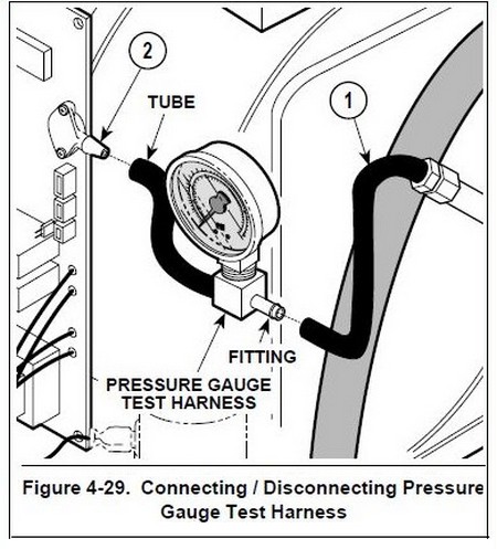
To connect Pressure Gauge Test Harness to sterilizer:
1. Disconnect tube (1) from pressure sensor (2).
2. Connect tube of Pressure Guage Test Harness to pressure sensor (2).
3. Connect tube (1) to fitting of Pressure Guage Test Harness.
To disconnect Pressure Gauge Test Harness from
sterilizer:
1. Disconnect tube (1) from fitting of Pressure Guage Test Harness.
2. Disconnect tube of Pressure Guage Test Harness from pressure sensor (2).
3. Connect tube (1) to pressure sensor (2).