To Get Started
Unplug the unit
Remove the Outer Cabinet
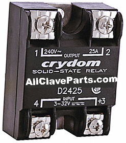
Label (by their location 1:4) then remove the four wires connected to the Solid State Relay
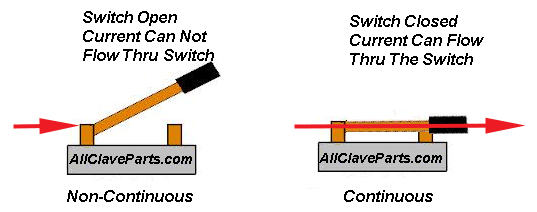
NOTE: An open electrical circuit means that there is a break in the continuity of the circuit. Circuits that are complete are considered closed
Set Your meter for continuity. If the reading between the points is Continuous (shows zero (0) on a digital meter or needle goes to the right approaching zero on an analog meter), then the circuit is closed. If the reading is Non-Continuous (shows the number 1 on a digital meter or the needle goes to the right (infinity) on an analog meter, then the cicuit is open

Using an ohmmeter,check for a short circuit between terminals 3 & 4 and 1 & 2 and 3& 1 and 4 & 2 and 3 & 2 and 4 & 1. Make sure there are no direct shorts. If a direct short is found in the SSR then replace it

- Next, using an ohmmeter, check for an open between terminals 1 & 2. Be sure to reverse the meter leads and check in the opposite direction.
- Repeat the procedure for terminals 3 & 4. If an open is found then replace the SSR
Replace the wires on the four connector of the SSR
If checking he Heat SSR then make sure that dip switch 4 (on the Digital Predg Board) is in the off or down position
Plug the unit in
Turn the unit on
Make sure the autoclave is sitting idle, no cycle is running. If necessary abort any cycle that may not have been completed
Take a DC voltage reading from terminal 3 on the Solid State Relay to ground
If checking the Heater or Dry Pump circuit both devices should be in the OFF mode and there should be a voltage reading between +3.5 and +5 volts DC
If checking the Water Pump circuit this device should also be in the OFF mode, however this reading should be between +10.5 and +12 volts DC.
Repeat this procedure with terminal 4 and you should have the same reading. A good reading indicates that the SSR is not turned on.
If terminal 3 does not read between +3.5 and +5 or +10.5 and +12 volts DC then check if the Power Supply is properly supplying these voltages
If terminal 4 does not read the correct voltage then, unplug the unit and remove the wire on terminal 4.
Turn the power back on and recheck terminal 4. If the reading is still not correct then replace the SSR.
If the reading is correct then check continuity between the terminal 4 wire and the appropriate connector: (unplug the unit when taking this reading)
- JP4 if checking the Heater SSR
- JP15 if checking the Water Pump SSR
- JP16 if checking the Dry Pump SSR with an Ajunc 3 board
- JP9 if checking the Dry Pump SSR with an Ajunc 2 board
If continuity checks out then there is a Control Problem
- With the Heaters or the Dry Pump ON and running, there should be a reading between +3.5 and +5 volts DC from terminal 3 to ground and a reading between 0 and 1 volt DC from terminal 4 to ground
- With the Water Pump ON and running, there should be a reading between +10.5 and +12 volts DC from terminal 3 to ground and a reading between 0 and 1 volt DC from terminal 4 to ground
- If the reading at terminal 4 does not switch from between +3.5 and +5 volts to between 0 and 1 volt when the Heaters or Dry Pump are ON then, check continuity between terminal 4 and the appropriate Ajunc board connector
- If the reading at terminal 4 does not switch from between +10.5 and +12 volts to between 0 and 1 volt when the Water Pump is ON then, check continuity between terminal 4 and the appropriate Ajunc board connector
- If continuity is good then there is a Control Problem
- If the reading at terminal 4 is between 0 and 1 volt then the SSR is on. The control side of the SSR is okay and the problem maybe on the load side
- For 110 volt units, with the unit on and the device in question in the OFF mode terminal 2 of the Solid State Relay should read between 110 and 125 volts AC to ground
- Terminal 1 should read near 0 volts AC to ground
- Reading across terminals 1 & 2 should show between 110 and 125 volts
- If terminal 2 does not read between 110 and 125 volts to ground then there is a problem with the line voltage wiring going to the SSR
- If terminal 1 shows the same voltage as terminal 2 then replace the SSR
- If there is a voltage reading less than 100 volts across terminals 1 & 2 then replace the SSR
- With the device in the ON mode, terminals 1 and 2 should each read between 110 and 125 volts to ground. Reading across terminals 1 and 2 should show close to 0 volts
- If terminal 2 does not show between 110 and 125 volts to ground then there is a problem with the line voltage wiring to the SSR
- If terminal 1 does not show between 110 and 125 volts to ground then replace the SSR
- If the reading across terminals 1 & 2 is greater than 1 or 2 volts then replace the SSR
- For 220 volt units, with the device in question in the OFF mode a voltage reading from terminal 1 to ground will read approximately 110 volts AC
- A reading from terminal 2 to ground will read approximately 110 volts AC
- A reading across terminals 1 & 2 should show between 220 and 235 volts. If terminals 1 and 2 do not each read approximately 110 volts to ground then there is a problem with the line voltage wiring going to the SSR
- If a voltage of between 220 and 235 volts is not present across terminals 1 & 2 then unplug the unit and remove the wires. Plug the unit back in and carefully take a reading across the wires. If a voltage between 220 and 235 is present then the SSR needs to be replaced. If the voltage is still incorrect then the problem is with the line voltage wiring going to the SSR
- With the device in the ON mode a voltage reading from terminal 1 to ground will read approximately 110 volts AC. A reading from terminal 2 to ground will read approximately 110 volts AC. A reading across terminals 1 & 2 should show a voltage near 0 volts AC
- If terminals 1 & 2 do not read approximately 110 volts to ground then there is a problem with the line voltage wiring going to the SSR
- If the voltage reading across terminals 1 and 2 is higher than 5 volts then replace the SSR


