SECTION 3-COMPONENTS BY FUNCTION
SECTION 3 - VALIDATOR PLUS DECSCRIPTION OF COMPONENTS BY FUNCTIONS
The door locking mechnaism prevents opening the door while the unit is pressurized. When the internal pressure equals atmospheric pressure, the door may be opened.
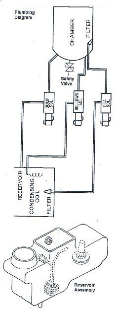
SAFETY VALVE
The safety valve, located on the top rear of the chamber, serves as backup protection in case of excessive pressure in the chamber. The safety valve opens only if chamber pressure exceeds 262 kPa (38PSI)
WARNING: The safety valve limits the maximum pressure to 262 kPa (38PSI). When replacing the safety valve, use only the type for which the unit was originally certified.
FILL/VENT SOLENOID
The fill/vent solenoid serves two purposes under software control:
- When in the fill process this solenoid allows water to enter the chamber and reservoir. It is open for a minimum of one minute during this process. It will be open for longer periods of time as each successive cycle is run based on the amount of reservoir in the reservoir.
If there is pressure in the unit at the time the fill cycle starts, then this this timer will be displayed until al pressure has been exhausted in order to facilitate rapid cycling of the unit. - When in the venting process, and the pressure is between 40 and 20 kPa, the fill solenoid opens to extract the water from the chamber through the bottom of the reservoir.
This solenoid is under software control and also serves two purposes:
- When in the venting process, this solenois is used to exhaust the pressure from the working value to 40 kPa.
- Whe in the air-bleeding process, this solenoid is used as an electronic bellows to remove the aur from the chamber in order to obtain saturated steam conditions
This solenoid is under software control. Its primary purpose is to rapidly exhasut residual chamber pressure. Normally, during the venting process, it will be opened at 20kPa, but it may be oopened during the filling process to exhaust residual pressures.
RESERVOIR ASSEMBLY
The reservoir assembly holds water for filling the autoclave chamber. The condensing coil in the assembly condenses steam coming from the chamber back into water for re-use in the next cycle
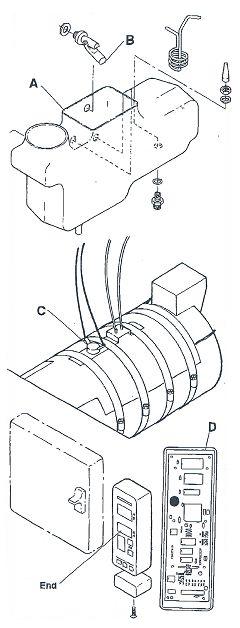
PLASTIC RESERVOIR
The one-piece plastic reservoir (A) holds approximately4.5 quarts (4.25 liters) of water. The reservoir drain tube coonects to the quick connect on the front of the sterilizer.
WATER LEVEL INDICATOR
A white plastic float mechanism (B) located inside the reservoir activates the low water light on the front panel when water level in reservoir drops.
HEATING ELEMENT The heating element © allows for even heating of the chamber. The microprocessor controls the power level for preheat, sterilization and drying cycles.
When the unit is turned on, the heaters are energized in preheat mode to minimize the warm-up time for the first cycle. Since the Validator Plus is capable of operating on 100/120/240 V~ and 50/60 Hz, the heaters are almost never fully on.
The heaters modulate on/off at a given duty cycle, and depend upon the incoming line voltage and frequency in every process. The heaters turn off at the completion of the drying cycle when "END" is displayed, if the door is not opened before the dry cycle is complete
MICROPROCESSOR/FRONT PANEL PRINTED CIRCUIT BOARD
There are two printed circuit boards (PCBs) located behing the front ocver, which contain the microprocessor (D) and the display driver/pushbutton controller.
These two PCBs are stacked one on top of the other. The top PCB is the microprocessor board, which has diagnostic LEDs and test points for monitoring the input/ouput status of the processor. The bottom PCB is the display driver/push button controller, and has no status indicators.
WARNING: If the bottom PCB is defective, return it with the display and cover intact. DO NOT attempt to remove it from the cover.
SAFETY FEATURES
The Validator Plus will automatically shut down for overpressure if the pressure display reaches 241kPa.
The Validator Plus will not start with the door open. The sterilization cycle will not continue if the door is op-ened after starting.
The door cannot be opened if 1kPa is present.
The plastic door cover protects the operator from being burned.
If the door is left closed, the heater power shuts off automatically when the drying cycle displays "END." If the door has been opened during the drying cycle, the unit returns to stand by heating.
DRIVER INTERFACE PRINTED CIRCUIT BOARD
The driver/interface PCB (E) is located on the right side (from front view) of the Validator Plus underneath the reservoir. This PCB is the one closest tot the rear of the unit
This PCB carries all of the necessary driver circuitry for the solenoids and the heater and the interfaces for all temperature switches and the pressure sensor.
This PCB has indicators and test pins for monitoring the input/output status of the board. This PCB also gives the status of the power supply PCB discussed below.
SWITCHING POWER SUPPLY PRINTED CIRCUIT BOARD
The power supply printed circuit board (F) is located on the right side (from front view) of the Validaotr Plus underneath the plastic reservoir.
This PCB is the one closest to the front of the unit. This PCB generates all of the low voltage supplies required to operate the unit and is responsible for making the conversion between the different line voltages and frequencies (100/120/240 VAC and 50/60 hz).
Status information for this PCB is provided on the Driver/Interface PCB described above
There are no products to list in this category.
Product Range
› Autoclave Troubleshooting249
› How To Test Heating Elements
› STATIM DETAILED TROUBLESHOOTING
› Pelton Crane Troubleshooting
› OCM and OCR Temperature Gauge
› VALIDATOR PLUS TROUBLESHOOTING
› SECTION 1- GENERAL SERVICE INFO
› SECTION 2 - THEORY OF OPERATION
› SECTION 3-COMPONENTS BY FUNCTION
› SECTION 6- PARTS REPLACEMENT
› VALIDATOR TROUBLESHOOTING GUIDE
› AMSCO 3000 BASIC TROUBLESHOOTING
› Castle Table Top Troubleshooting
› CHEMICLAVE 5000 TROUBLESHOOTING
› Infant Incubators & Warmers138
› Orthopedics & Physical Therapy277
Important Links
- › For Missions Only
- › How To Repair Your Autoclave PC Control Board
- › OCM OCR Exploded View - UPDATED
- › Spore Test Failure
- › Sterilizer FAQ
- › Shipping Policy
- › Return/Cancellation Policy
- › Registered Trademarks
- › Disclaimer
- › Cleaning Statim Water Pump Filters
- › Payment Methods
- › International Customers
- › How To Test Autoclave Heating Elements
- › Testimonials
- › Can't Find The Door Gasket (Seal) You Need?
- › Used Autoclaves - What To Look For