


SECTION 6- PARTS REPLACEMENT
SECTION 6 - VALIDATOR PLUS PARTS REPLACEMENT
NOTE: Refer to the Validator Plus 8 & Validator Plus 10 Parts Lists When Ordering Parts.
WARNING: Before Servicing, Turn Off Master Power Switch On Rear Cover And Disconnect Power Plug From Outlet.
NOTE: Refer to the Validator Plus 8 & Validator Plus 10 Parts Lists When Ordering Parts.
WARNING: Before Servicing, Turn Off Master Power Switch On Rear Cover And Disconnect Power Plug From Outlet.
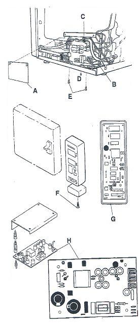
I. DRIVER INTERFACE CIRCUIT BOARD
- Remove outside cover. Remove clear plastic shield (A) from Driver/Interface Circuit Board
- Disconnect the cable connectors from the printed circuit board (B)
- Disconnect silicone steam line tubing from transducer (C)
- Remove screw (D) and nut from triac
- Pull bracket away from unit. Remove mounting screws (E) holding brackets. Then remove Driver/Interface Board from bracket.
- Install new Driver/Interface Printed Circuit Board
- Re-attach steam line tubing. Apply heat sink to triac, then secure with screw and nut previously removed. Secure mounting bracket with screws. Reconnect cables. Reinstall clear plastic shield over circuit board and unit cover.
II. MICROPROCESSOR/FRONT PANEL PRINTED CIRCUIT BOARD
- Remove two screws (F) at bottom of front panel.
- Pull front panel out at bottom and lift to remove.
- Disconnect the ribbon cable and the printer cable from the MPU/Front Panel PCB (G)
- Replace the MPU board by lifting under the long side and rock from side to side.
III. SWITCHING POWER SUPPLY PRINTED CIRCUIT BOARD
- Remove outside cover.
- Disconnect cables from power supply PCB H
- Reconnect new PCB in reverse order of preceding directions.
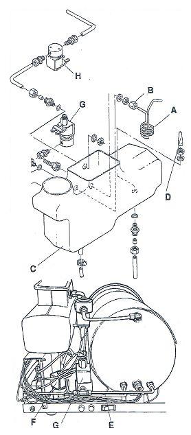
IV. CONDENSING COIL
- Remove outside cover. Locate Condensing Coil (A)
- Unscrew compression nut (B) connecting condensing coil to coupling.
- Remove condensing coil
- Place new compression nut and sleeve over end of new condensing coil.
- Insert new condensing cvoil into coupling and tighten nut.
V. PLASTIC RESERVOIR
- Remove outside cover.
- Drain water from reservoir (C)
- Disconnect all tubing on outside of reservoir
- Remove Condensing Coil (A) and float sensor
- Unscrew filter (D) inside reservoir
- Remove ½ " nut in bottom of reservoir
- Replace new plastic reservoir in reverse order of preceding directions.
- Fill new plastic reservoir with distilled water.
VI. FILL/VENT, DUMP,BELLOWS SOLENOIDS
- Remove outside cover.
- Disconnect lead to Drive?Interface printed circuit board from Solenoid
- Disconnect brass tubing (E) and save compression fittings
- Remove two mounting screws securing Fill/Vent (F), Bellows Solenoid (G) or Dump Solenoid (H)
- Install and connect new Solenoid Assembly in reverse order of preceding directions.
NOTE: Match orfice size of new solenoid tp the size of the defective solenoid
Fill/Vent ---Orfice Diameter 3/16"
Dump ------Orfice Diameter 5/16"
Bellows --- Orfice Diameter 1/8"
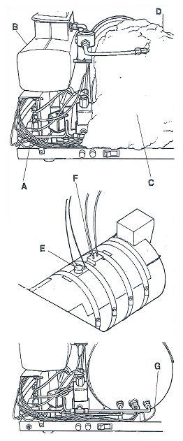
VII. OVERHEAT PROTECTOR AND SURFACE SENSOR
- Remove outside cover
- To replace overheat protector and surface center, unplug all connectors from Driver/Interface Board (A)
- Drain reservoir (B). Turn unit upside down. Take off bottom panel and remove chamber insulation (C)
- Remove Overheat Protector or Surface Sensor by loosening straps (D) around chamber element.
VIII. HEATER ELEMENT
- Remove outside cover.
- Disconnect heater connections from Driver/Interface printed circuit board.
- Drain reservoir. Turn unit upside down. Remove screws holding bottom pan to chamber support. Then remove bottom pan.
- Remove overheat protector (E) and heat sensor (F)
- Remove metal straps securing insulation jacket to heater (G) and chamber. Remove insulation. Remove large hose clamps securing copper plates to chamber.
- Remove Heater (located between copper plates).
- Replace new Heating Element in reverse order of preceding directions. Install Heater with printed information away from the chamber.
NOTE: Make sure that all surfaces that mate with element are clean and smooth
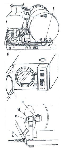
IX. STEAM SENSOR
- Remove Outside Cover
- Disconnect sensor plug (H) from driver board
- Unscrew sensor (I) and replace, using pipe joint compound on threads.
- Replug unit and check function
X. CHAMBER AND DOOR ASSEMBLY
Note: Service to the chamber and door assembly should not be performed in the field. Service and reapir of the chamber and door assembly should be performed by the factory only, to assure continued compliance with ASME requirements.
XI. DOOR GASKET
- Open door to expose gasket (J)
- Remove old Door Gasket.
- Wipe new Door Gasket with Omni-Cleaner Plus.
- Install new gasket by starting at bottom of door and working door gasket into position.
- Remove outside cover.
- Disconnect the flex tubing (K) and unscrew pipe nipple (L) to reuse on new safety valve.
- Unscrew safety valve (M) and brass elbow (N) from chamber
- Unscrew old safety valve (O) from elbow.
- Apply fresh pipe thread sealant to elbow and chamber screw threads
- Insert new safety valve in reverse order of preceding directions. Be sure to tighten safety valve and properly align with opening in pan. Reconnect flex tubing to the safety vaalve nipple, taking care to extend the tube through the bottom of the unit
WARNING: The safety valve limits the maximum pressure to 262 kPa (38 PSI) on the Validator Plus. When replacing the safety valve, use only the type for which the unit was originally certified.
There are no products to list in this category.
Categories
Important Links
- › For Missions Only
- › How To Repair Your Autoclave PC Control Board
- › OCM OCR Exploded View - UPDATED
- › Spore Test Failure
- › Sterilizer FAQ
- › Shipping Policy
- › Return/Cancellation Policy
- › Registered Trademarks
- › Disclaimer
- › Cleaning Statim Water Pump Filters
- › Payment Methods
- › International Customers
- › How To Test Autoclave Heating Elements
- › Testimonials
- › Can't Find The Door Gasket (Seal) You Need?
- › Used Autoclaves - What To Look For
Information


